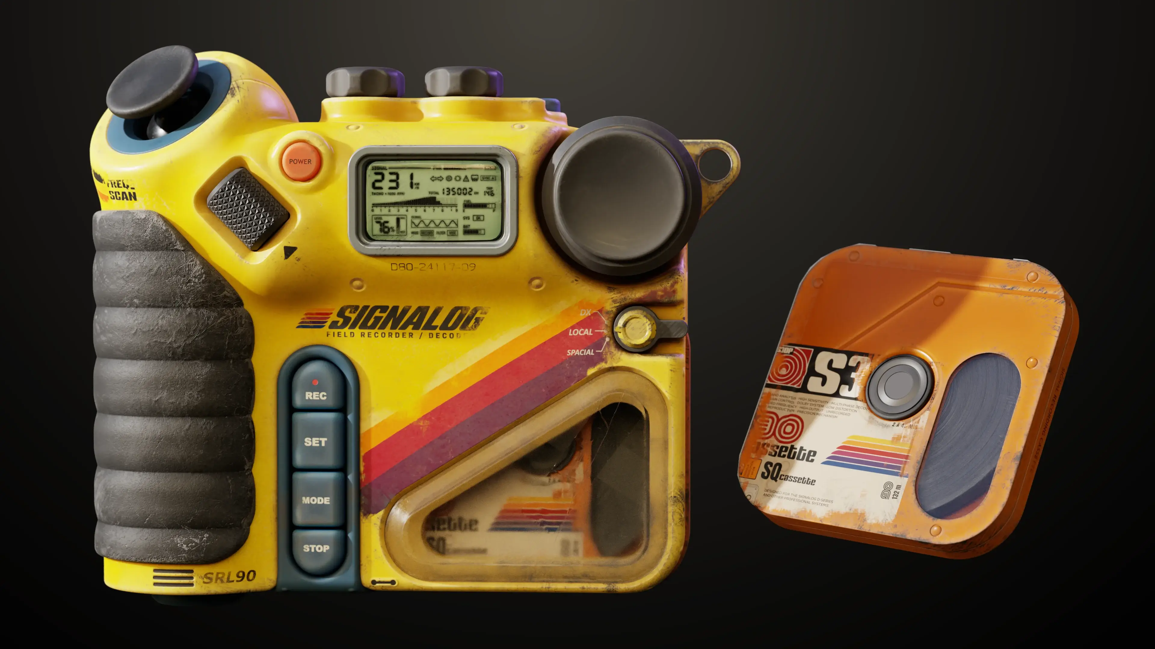





In this tutorial, I’ll walk you through the workflow using a retro sci-fi field recorder. Think of a handheld signal decoder that has been dragged through a few too many expeditions. We’ll start with a decimated mesh, generate UVs, clean up the bake, then add editable panel lines, tape and graphics.
The idea is simple: get the technical setup working, keep your detailing non-destructive, and only add complexity when the asset needs it.
Step 1: Import your mesh and generate UVs automatically
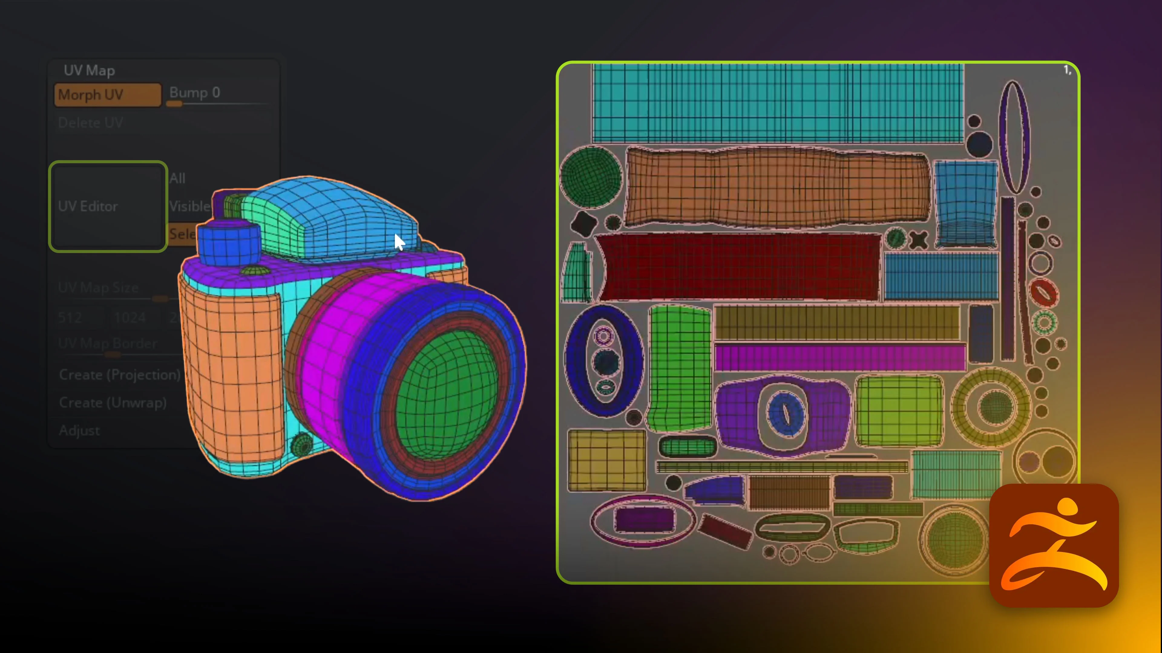
The starting mesh is a decimated, triangulated version of the high-poly model. It isn’t clean retopology, but for this asset I can take it straight into Painter and generate UVs automatically instead of stopping for a separate retopology and unwrap pass.
In the New Project window:
- Select your low-poly mesh.
- Use the OpenPBR template, which is the default in the release used here.
- Enable the UV Tile Workflow to give the asset more texture space.
- Enable Auto-unwrap and open its options.
- Choose the Hard-surface unwrap mode.
- With UV tiles enabled, set the maximum tile count. For this recorder, I use 10.
- Leave the remaining options at their defaults, confirm the settings and create the project.
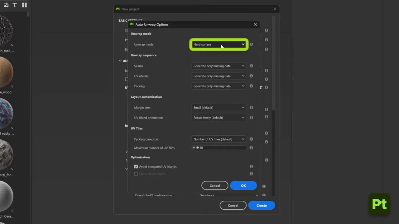
The recorder has roughly nine or ten different materials, which is why I choose that maximum for this example. Treat it as a project-specific setting rather than a number you need to copy for every asset.
That’s the first time saver: load the mesh, adjust a few settings, and you have a project ready for texturing.
Step 2: Bake mesh maps from the high-poly model
Next, bake the mesh maps. These bring the high-poly detail onto the low-poly surface and give Painter’s generators the information they need to work with the asset.
I’ll use the recorder’s cassette component to make the process easier to read. The high-poly version has grooves, fasteners and panel details, while the low-poly version is deliberately simple.
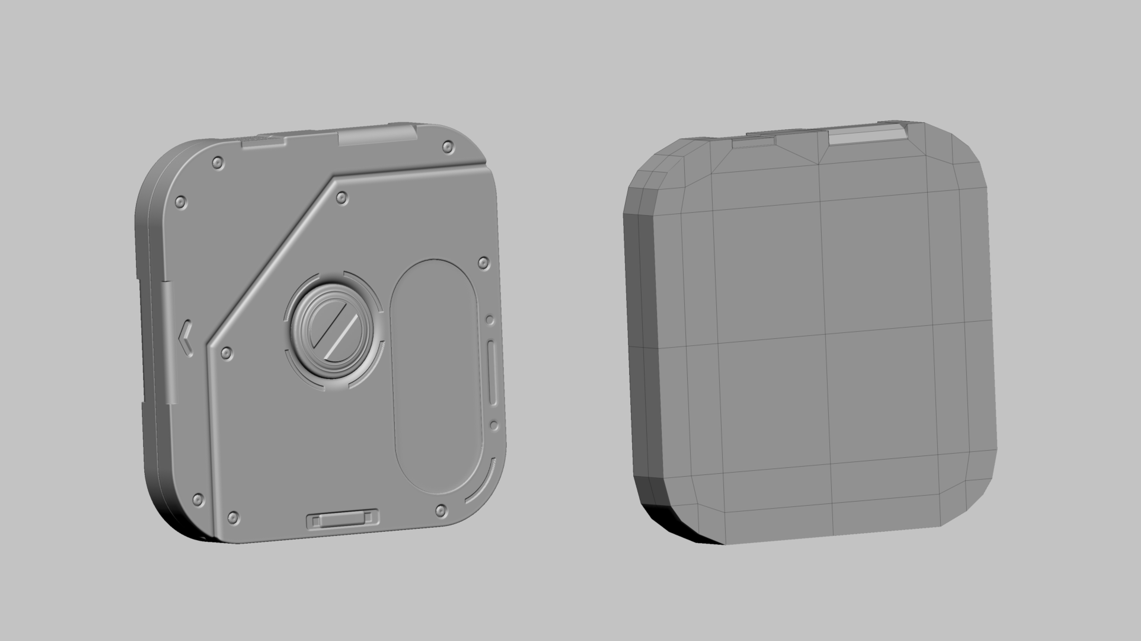
- Select the cassette’s texture set.
- Open the baking interface using the Bake icon.
- In Common Settings, load the high-poly model.
- Leave the remaining settings at their defaults for this first pass.
- Click Bake.
The baking interface separates Common Settings from Mesh Map Settings. Within Common Settings, you’ll find the main settings, cage controls and skew correction controls.
Once the bake finishes, hide the high-poly model, cage and wireframe so you can inspect the result without overlays. Don’t stop at the overall appearance. Zoom into small details, particularly near corners and edges. A bake can look good from a distance while still stretching individual grooves or screw heads.
Step 3: Paint skew correction where details distort
If a baked detail looks stretched or pulled towards an edge, the projection direction may be the problem. This is where Paint Skew Correction becomes really useful.
First, use the view icon beside the normal map to isolate it. Then zoom into a distorted detail and open the Skew Correction tab.
- Click Paint Skew Correction.
- Switch the correction method from Mesh normal based to Face normal based.
- Adjust the normal-line display so you can clearly see the projection directions.
- Paint over the affected detail.
- Release the stroke and inspect the automatically rebaked result.
Why change the correction method? Near an edge, a vertex can belong to both the top and side faces. Its normal gets averaged between those surfaces, so instead of pointing straight out from either face, it leans towards the edge. That leaning can distort the high-poly detail during baking.
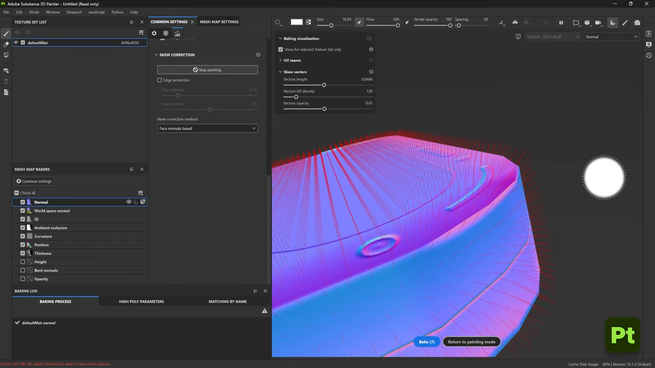
Using face normals gives the correction a different reference rather than relying on the same averaged mesh normals that caused the skewing.
You can reduce the number of displayed lines, spread them out or increase their length. These are display adjustments, but they make it much easier to understand what is happening around the corner.
Auto Rebake is enabled by default in this painting mode. As soon as you finish a stroke, Painter updates the bake. Green lines in the painted area indicate the corrected directions, so you can judge the result immediately.
The brush behaves like Painter’s texturing brushes. Use the controls across the top for quick changes, or right-click for the rest of the brush settings. For a simple part, switch to Polygon Fill and choose UV Chunk to correct a whole UV island with one click. On this cassette, that’s a quick way to handle the back surface.
Step 4: Use Edge Protection to clean up UV-seam artifacts
Skew correction can fix a stretched detail and still introduce an odd artifact at a nearby seam. If that happens, check whether the problem follows a UV cut.
Correcting the projection also removes some of the normal averaging along the edge. Around a seam, that can create a new shading problem even though the original detail is now projecting correctly.
The fix is straightforward:
- Enable Edge Protection in the skew correction controls.
- Adjust its sliders if the corner still needs refinement.
- Inspect the updated bake around the seam and adjoining surfaces.
Keep these two fixes separate in your mind: skew correction handles distorted projection; Edge Protection helps preserve the edge treatment where that correction creates artifacts.
Step 5: Add editable panel lines with Ribbon paths
With the setup out of the way, we can move on to the fun part. On the textured recorder, I use paths to explore extra panel divisions and manufacturing cuts without committing those details to the mesh.
Select the Path tool and set its type to Ribbon. A Ribbon creates one continuous run, allowing you to stretch an image or an SBSAR material across the whole path.
- Search for line in the brush library.
- Choose Shutter Parting Line Groove.
- Place a few points on the model to define the panel line.
- In the material controls, turn off colour to make the groove easier to evaluate.
- Return to the path settings and adjust Stroke Width.
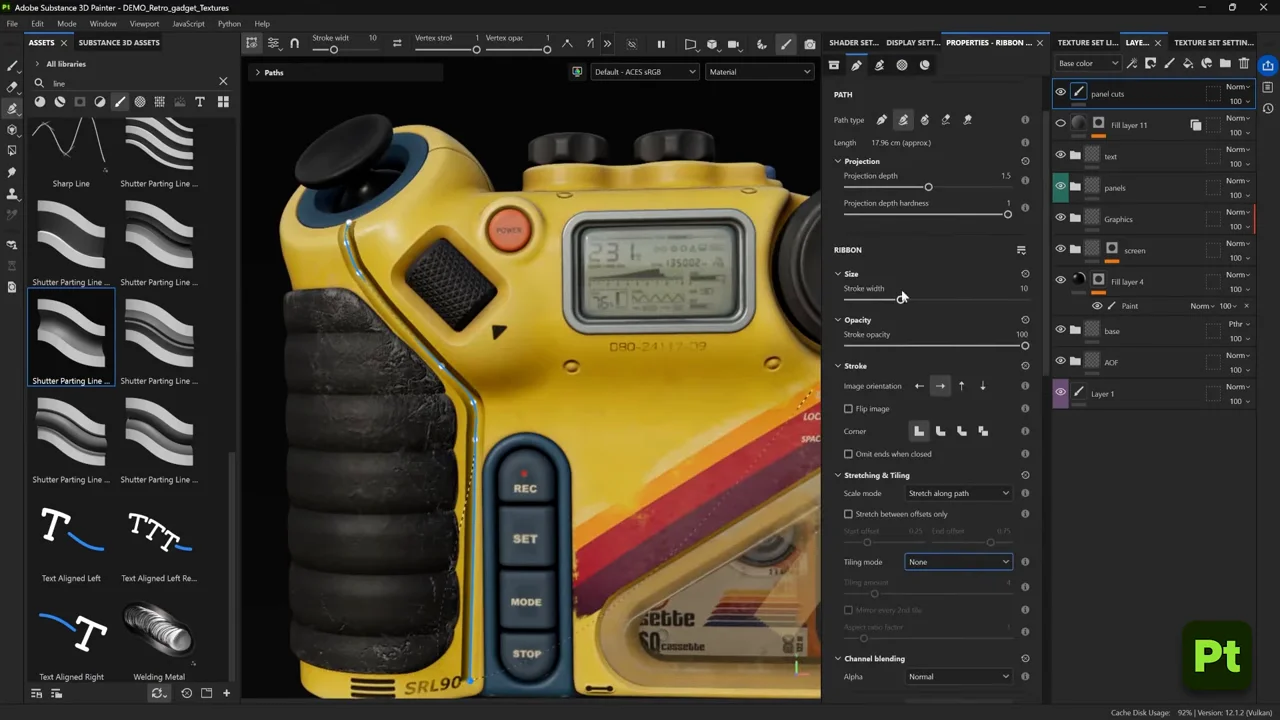
You don’t need to get the width perfect on the first attempt. That’s the benefit of this workflow: the path stays editable, so you can adjust the line after placing it.
I use the same approach for the extra panelling around the top of the recorder and other cut lines across the housing. It’s a quick way to test whether an additional division actually helps the design before spending more time on it.
Step 6: Turn a path into gaffer tape by swapping presets
Paths aren’t limited to panel grooves. You can keep the same path and replace its appearance with something completely different.
Place another short path across the recorder. It initially inherits the previous settings, so it still looks like a panel cut. With that path selected, open the Hard-surface presets and choose Tape Gaffer.
The selected path updates immediately. From there, refine the tape:
- Adjust its width or overall size.
- Tweak how much the tape sticks to itself.
- Add more wrinkles.
- Roughen the ends for a less tidy finish.
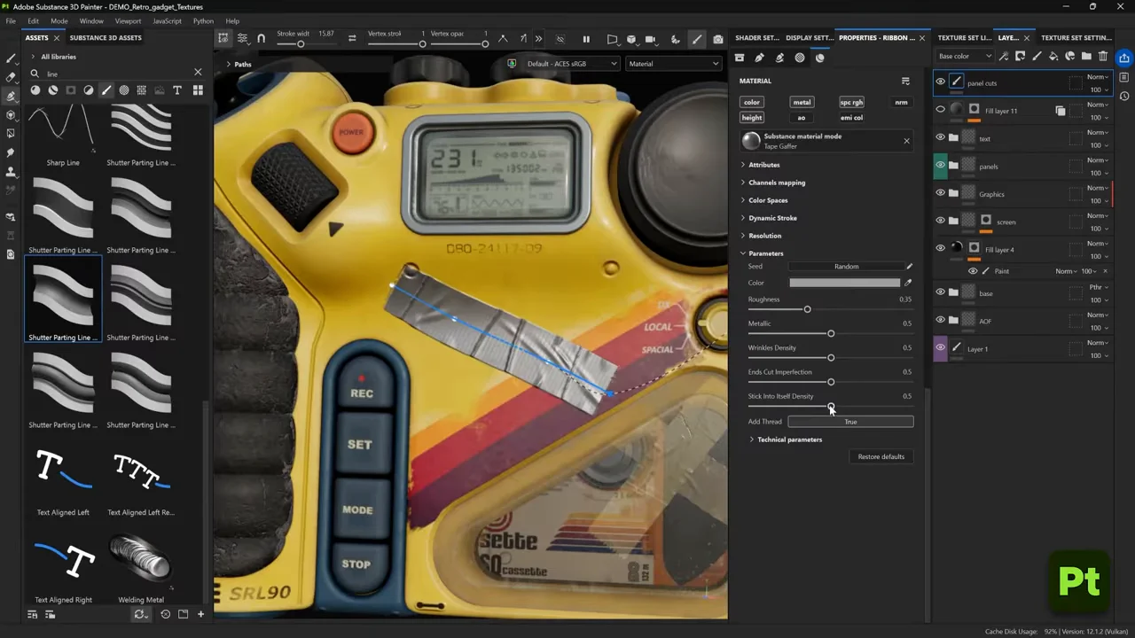
The important part is that this is still non-destructive. You can reshape the path, choose another tool to replace its appearance, or swap to a completely different preset.
That makes it a useful way to explore details. A panel line suggests construction; a piece of wrinkled tape suggests use and repair. You can test both without rebuilding the underlying asset.
Step 7: Bring Illustrator graphics into Painter and keep them linked
Logos, labels and coloured graphics can give a prop a much stronger identity. For this recorder, I created a fictional brand in Adobe Illustrator, with several logo variations stored in the same file.
Put each variation on its own artboard. This makes it easy to switch between them later in Painter.
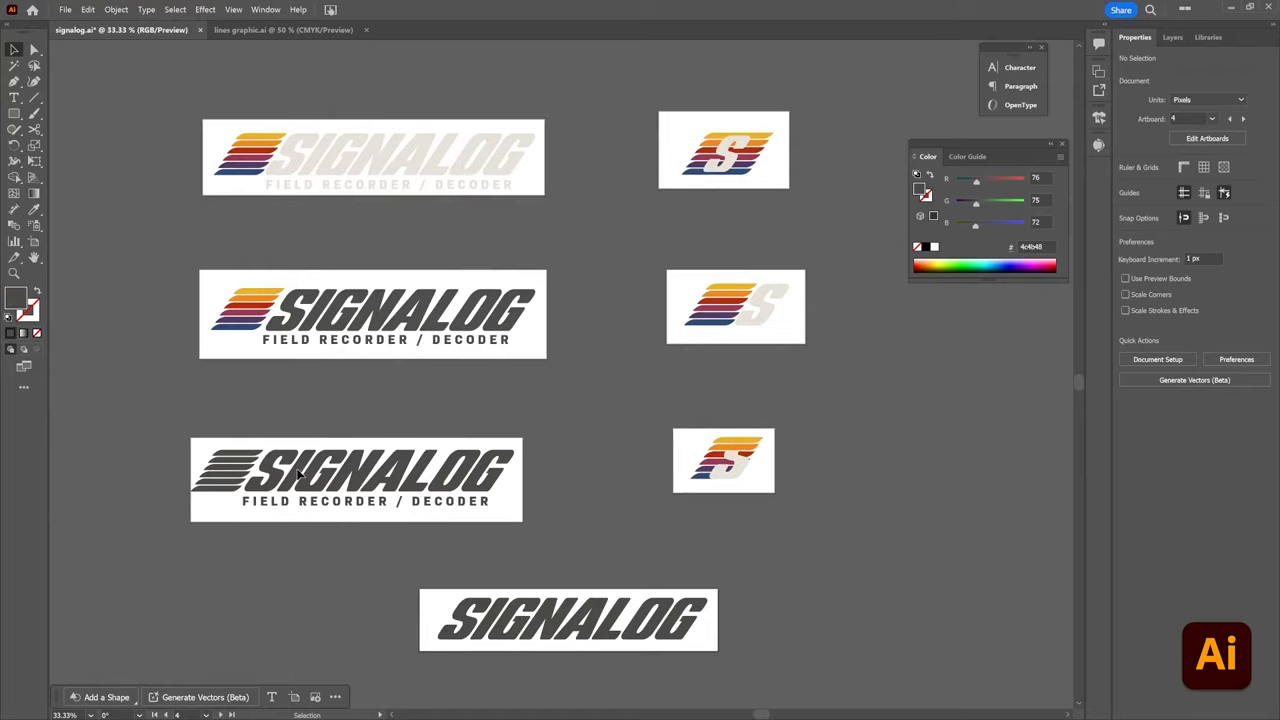
Drag the entire Illustrator file into Painter, then use the move and scale manipulators to place the logo on the housing.
In this example, the first version uses light lettering. The placement works, but the lettering doesn’t read particularly well against the yellow plastic. Rather than importing another file, switch artboards:
- In the asset panel, open the Auto Update controls.
- Make sure both Assets panel and Resources used in this project are enabled.
- Scroll to the imported asset’s file-specific settings.
- Use the artboard dropdown to choose another variation. Here, I choose Artboard 5.
The logo updates immediately, making it easy to compare the lighter and darker versions directly on the model.
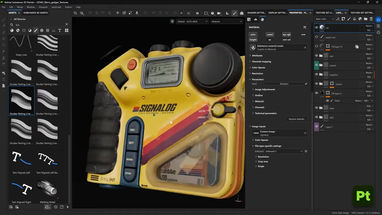
The same workflow works for the decorative stripes. Open the original Illustrator file, change the colour or width of the lines, then save. With auto update enabled, those changes appear back in Painter.
This keeps the graphic design flexible. You can judge a variation against the actual material and geometry, then return to Illustrator for a quick adjustment.
Step 8: Wrap decals around curved surfaces
A graphic can look fine on a flat section and start fading at the edges when you enlarge it over a curved area. The reason is simple: you’re projecting a flat plane onto a surface that turns away from it.
For the label near the recorder’s upper dial:
- Drag the graphic onto the model.
- Choose Base Colour when prompted.
- Move and scale it over the curved housing.
- Click Warp to Geometry in the top toolbar.
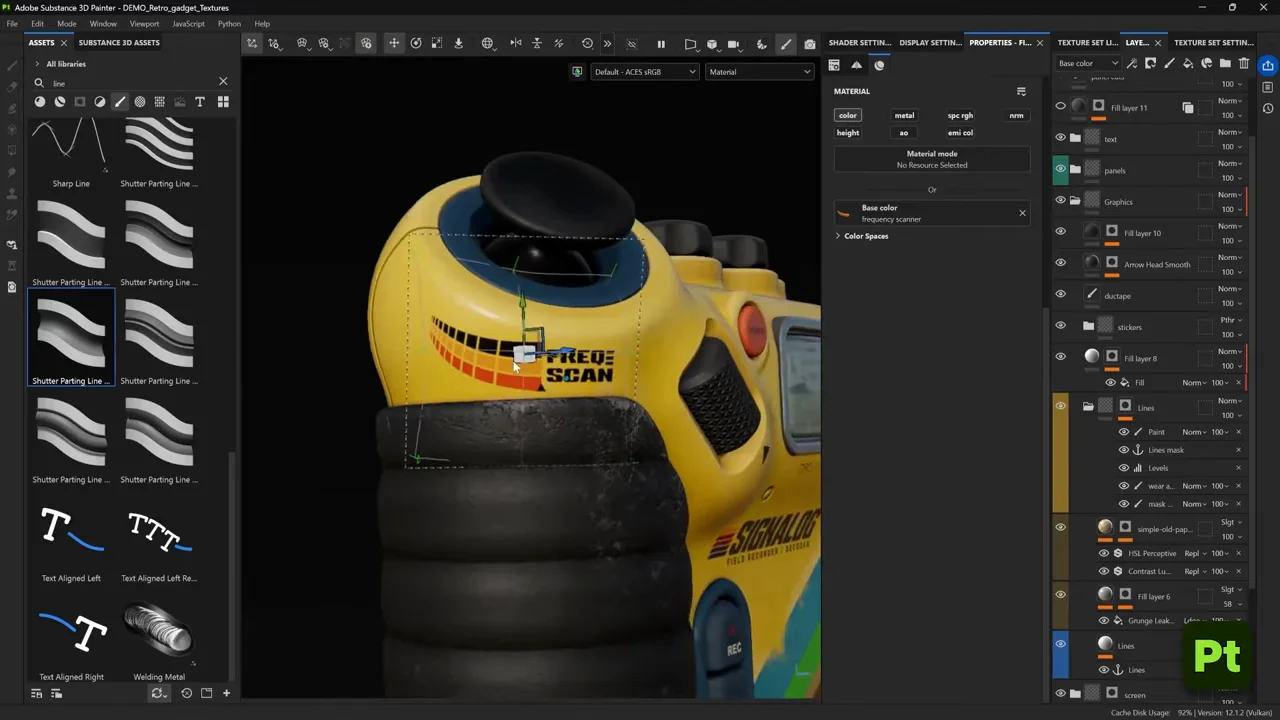
The graphic now follows the volume of the geometry. You can continue moving, rotating and scaling it to refine the placement.
It’s a small change to the workflow, but a very useful one when you want a label to sit around a rounded part rather than appear confined to a flat projection.
Step 9: Flatten heavy layer groups while keeping the originals
As the asset develops, layers, masks and effects can make the project heavy. Flatten Group gives you a way to simplify the working stack without throwing away the original setup.
- Select the layers you want to consolidate.
- Right-click and group them.
- Right-click the new folder.
- Choose Flatten Group.
Painter merges the group’s result into a single layer and keeps the originals in an automatically hidden folder. You get a lighter working result while retaining the source layers if you need to revisit them.
I select everything here to demonstrate the feature, but the process starts with whichever layers you want to flatten.
By this point, the simple mesh has become a much more characterful prop. Baked details establish the construction, while panel lines, graphics, tape and surface wear suggest how the recorder has been used.
Why this workflow works: it removes friction from setup and keeps the creative decisions flexible. Auto-unwrap gets the mesh ready, skew painting cleans up projection problems, paths let you explore details, and linked Illustrator files make graphic changes quick.
Start with a clean bake, keep your additions editable, and use each detail to give the object a little more history. That’s where hard-surface texturing becomes more than finishing a mesh: it starts telling a story.