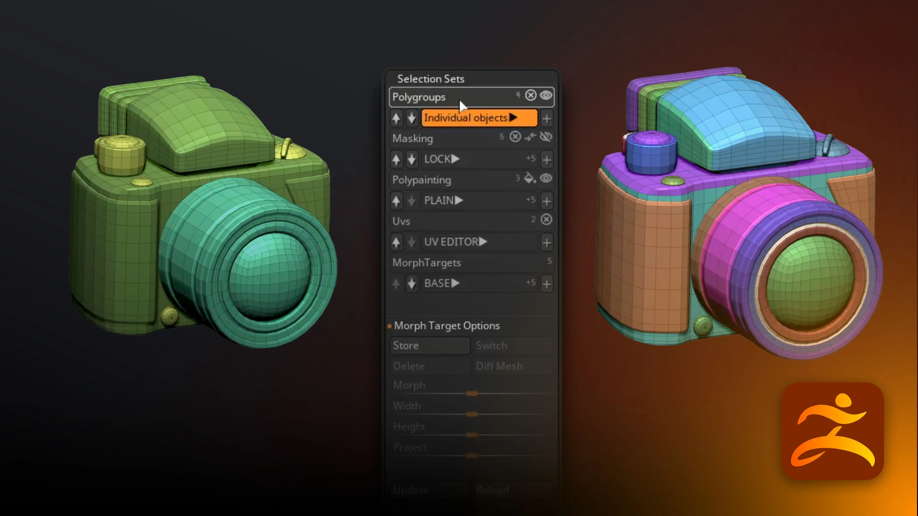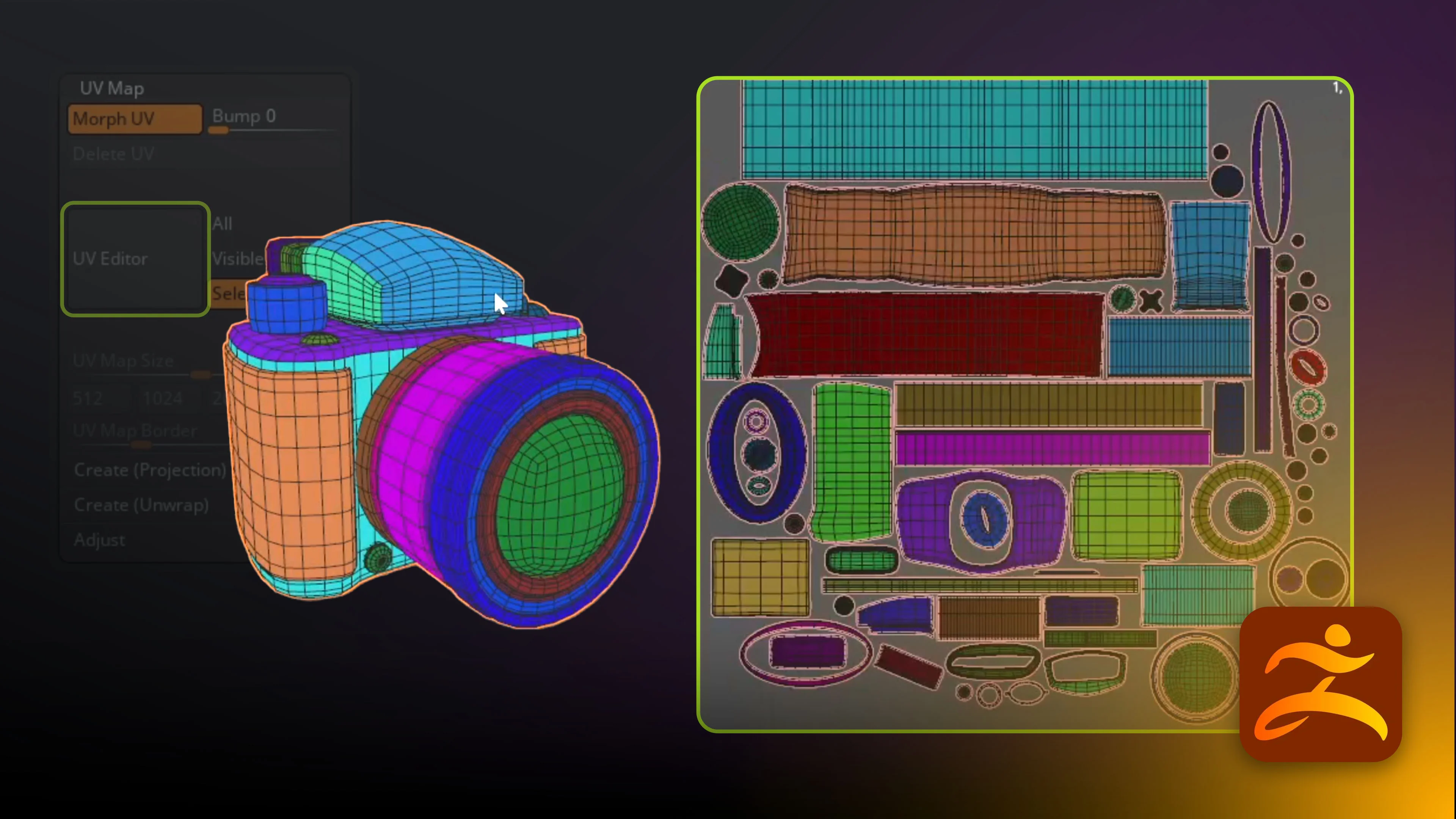





This workflow uses a simple camera asset to keep the process clear. The same stages apply to more complex models: start with useful PolyGroups, unwrap, check the result, edit the problem areas and pack everything once the islands are ready.
What you’ll need
- ZBrush 2027. The workflow demonstrated here uses version 2027.0.1.
- A model with PolyGroups that separate useful surface regions. Camera Asset here.
- Optional: a custom checker texture for inspecting distortion.
The workflow at a glance
- Send your subtools to the UV Editor.
- Generate a starting layout with Unwrap by PolyGroup.
- Use selections and seams to repair difficult areas.
- Check distortion with a texture and diagnostic displays.
- Align, rectangularize and pack your islands.
- Apply the edits back to ZBrush.
Step 1: Prepare your PolyGroups and open the UV Editor
Open Tool > UV Map. The UV Editor button lives here, alongside options for sending the selected, visible or all subtools into the editor.
Before opening it, enable PolyFrame and inspect your PolyGroups. These become the starting boundaries for a PolyGroup-based unwrap, so the grouping you choose makes a difference. Large groups give you broader regions; more specific groups let you separate individual parts.
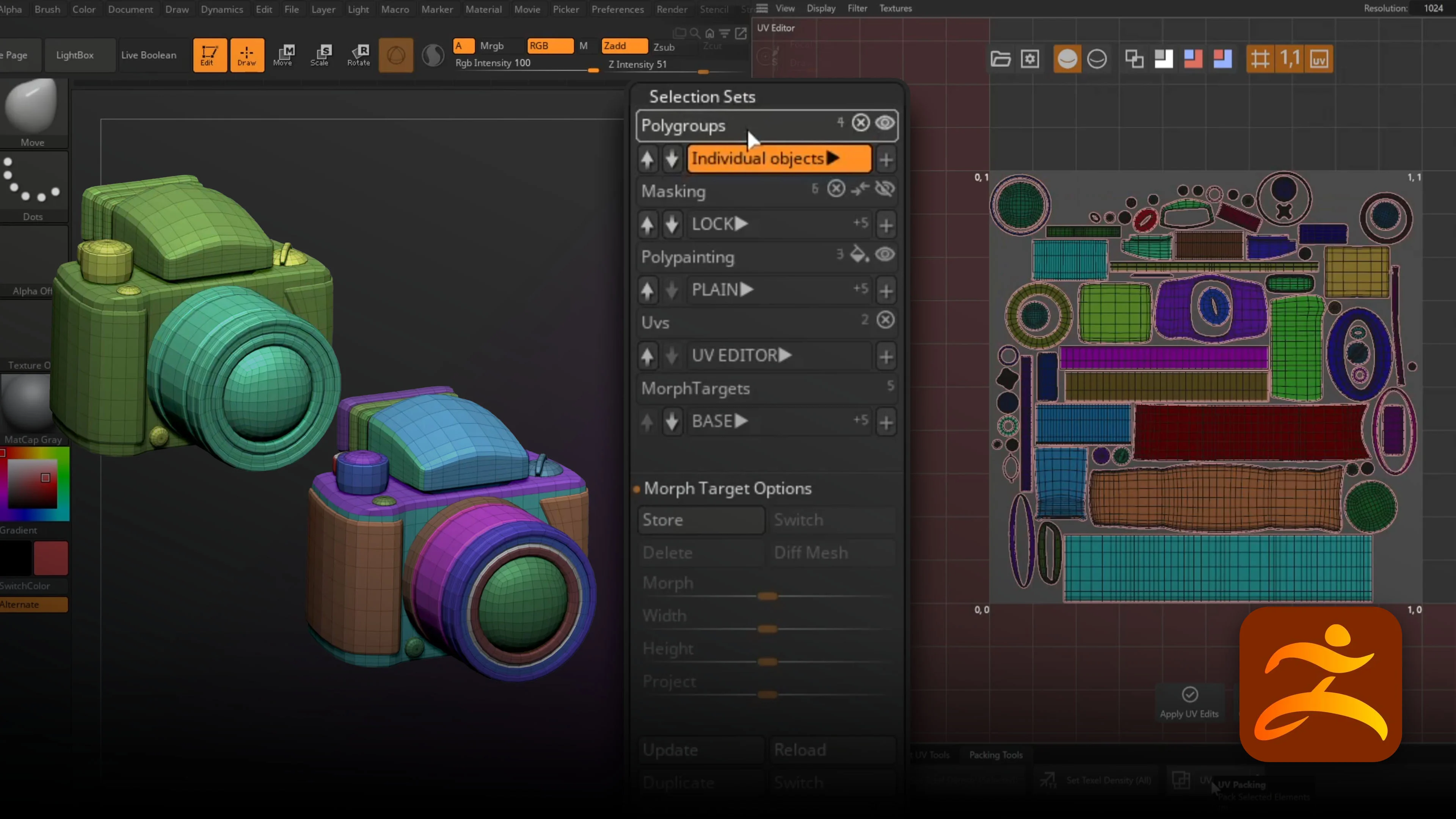
For the camera, groups distinguish areas of the body, lens and smaller components. Selection Sets can help switch between different PolyGroup arrangements if you have already stored them.
You don’t need to delete existing UVs to use the editor. If you want to compare approaches, generate a UV Master layout first with PolyGroups enabled, inspect it with Morph UV, then save that layout in a UV selection set. You can keep the quick unwrap as a reference while building a more controlled version.
Step 2: Frame the model and learn the workspace
The UV Editor opens in a separate window. It can feel like another application at first, but the workspace is straightforward:
- Object list: the subtools you sent from ZBrush.
- 3D viewport: the model and its surface selections.
- 2D view: the UV islands you will edit and arrange.
- Attributes: contextual settings for the selected object or tool.
If the model seems to be missing, press H to frame it. A model that is comfortable to sculpt in ZBrush may initially appear very small here.
Navigation uses familiar right-mouse controls:
- Right-drag: rotate.
- Ctrl + right-drag: zoom.
- Alt + right-drag: pan.
- Mouse wheel in the 2D view: zoom the UV layout.
The tags beside the object name control access to information such as PolyGroups and texture display. Click the PolyGroup tag to see the grouping carried over from ZBrush.
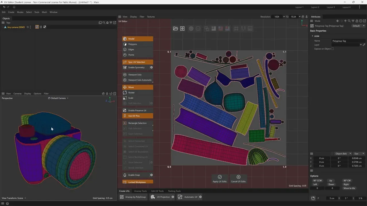
One useful interface rule: a gear icon opens additional settings. A small triangle indicates alternative tools… click and hold to reveal them.
Step 3: Generate a starting layout with Unwrap by PolyGroup
Select the model and click Unwrap by PolyGroup. If you deliberately want to discard the incoming layout first, use Reset UVs.
This follows the familiar UV Master idea: use the PolyGroup boundaries to separate the surface into islands. The difference is that the new editor uses Maxon’s UV technology, also used in applications such as Cinema 4D, and gives you tools to refine the result afterwards.
For a quick asset, this may already be enough. You can apply the UV edits and return to ZBrush. For a cleaner layout, treat it as a first pass rather than a finished solution.
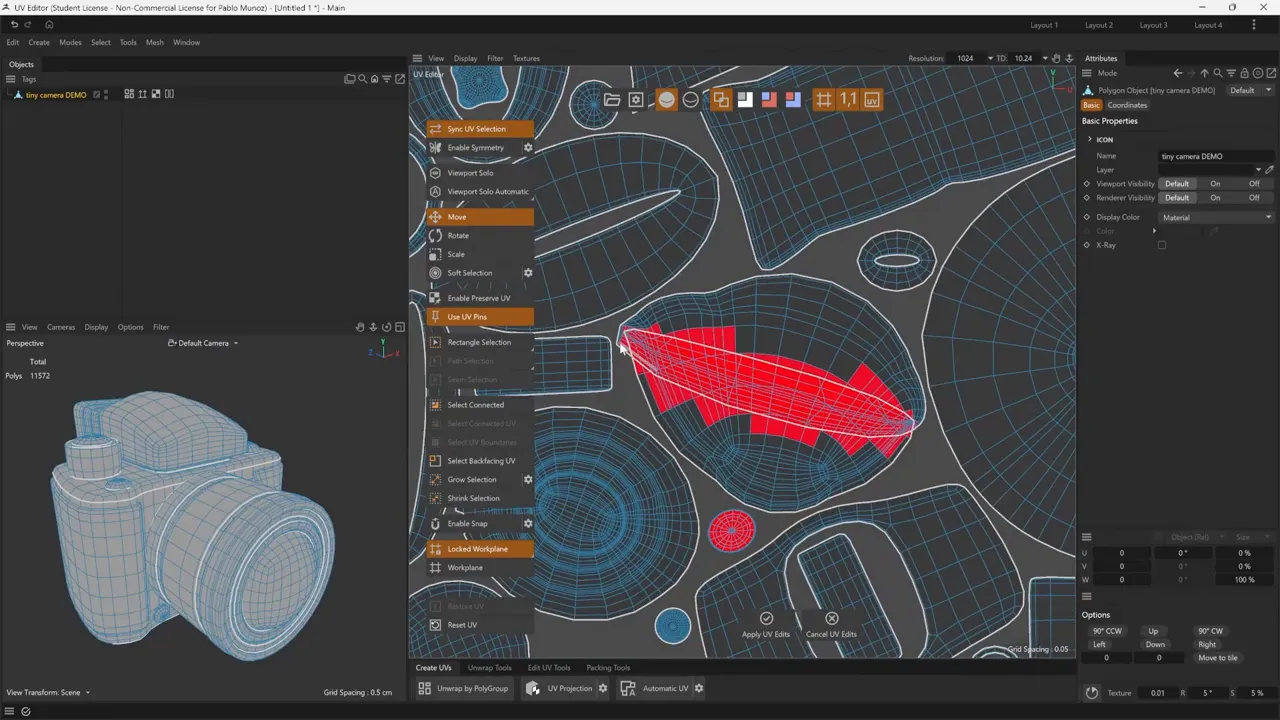
Enable the overlapping polygons display and inspect the red areas. On this camera, a couple of regions need additional cuts before they can flatten properly. Packing alone won’t fix an island that overlaps itself.
Step 4: Get comfortable selecting islands and components
Switch between Polygons, Edges and Points depending on the task. Polygons are convenient for selecting islands; edges are what you’ll use to define seams.
- Click: select an individual component.
- Shift: add components to the selection.
- Grow / Shrink Selection: expand or reduce a selected region.
- Select Connected: extend the selection across connected UVs.
- Double-click a polygon in the 2D view: select its entire UV island.
Keep Sync UV Selection enabled so the selected UVs are highlighted on the 3D model too. This makes it much easier to identify what each island represents. Be aware that selecting connected polygons in the 3D viewport can select the connected object rather than just the UV island you intended.
Rectangle, lasso, brush and polygon selection tools are also available. Double-click empty space to deselect. If individual clicking stops behaving as expected after using a selection tool, switch back to Move, Rotate or Scale.
For multiple subtools, Viewport Solo isolates the selected object. Automatic Solo can isolate objects as you select them. Symmetry is useful for genuinely symmetrical regions, such as the lens, but leave it off for asymmetrical parts. Its gear menu includes planar, topology and radial options.
Step 5: Move and rotate islands… scale with care
The transform shortcuts are simple:
- W: Move.
- E: Rotate.
- R: Scale.
Use Move to pull a troublesome island away from the layout while you work. Use Rotate to inspect or orient it, and hold Shift while rotating for stepped snapping.
Be careful with scaling. Enlarging one island independently changes its texel density relative to the rest of the model. That can leave one surface with plenty of texture detail and another with noticeably less.
For local adjustments, Soft Selection lets nearby UVs follow a selected point with a falloff. This is particularly useful for organic surfaces. Open its settings, switch from All to Centre for a centred influence, then reduce the radius until the affected area is local enough.
You can also adjust strength and choose falloffs such as Linear, Dome or Bell. If the whole layout moves, the radius is probably too large. Pinning points is another option when you want to hold part of an island in place while adjusting its interior.
Step 6: Mark seams and re-unwrap problem areas
The tool groups follow a useful order: Create UVs, Unwrap, Edit UVs and Packing. Once you have a starting layout, move to the Unwrap tools to define better cuts.
- Switch to Edges.
- Select the edge or path where you want a cut.
- Click Mark as Seam.
- Switch back to Polygons and select the affected UV region.
- Run UV Unwrap and Relax.
Double-click an edge to select a continuous loop. Hold Shift while adding more loops. For less regular routes, Path Selection helps build a selection across the surface.
Seam Selection combines selecting and marking: draw the route, release, and it becomes a seam. This is handy when you already know where the cut belongs. Hold Ctrl with that tool to remove seams when correcting a route.
On cylindrical parts such as the camera dials and lens rings, add a cut along the side so the surface can open into a strip. Place it somewhere less visible when possible. Zoom in and check for tiny missed edges… one uncut connection can prevent the region from opening as intended.
Marking a seam doesn’t flatten the UVs by itself. You still need to unwrap the affected region. Make a selection for a local repair; with nothing selected, the unwrap operation can affect the whole layout.
Step 7: Weld islands when you need more continuity
Sometimes the cuts produce a small floating island that would be more useful attached to a neighbouring section. Open Edit UV Tools > Weld UVs and click the corresponding boundaries to join them.
After welding, return to Move, select the joined region and run UV Unwrap and Relax again. If a small section needs to connect to two larger pieces, you can split it with another seam and weld each part to the appropriate neighbour.
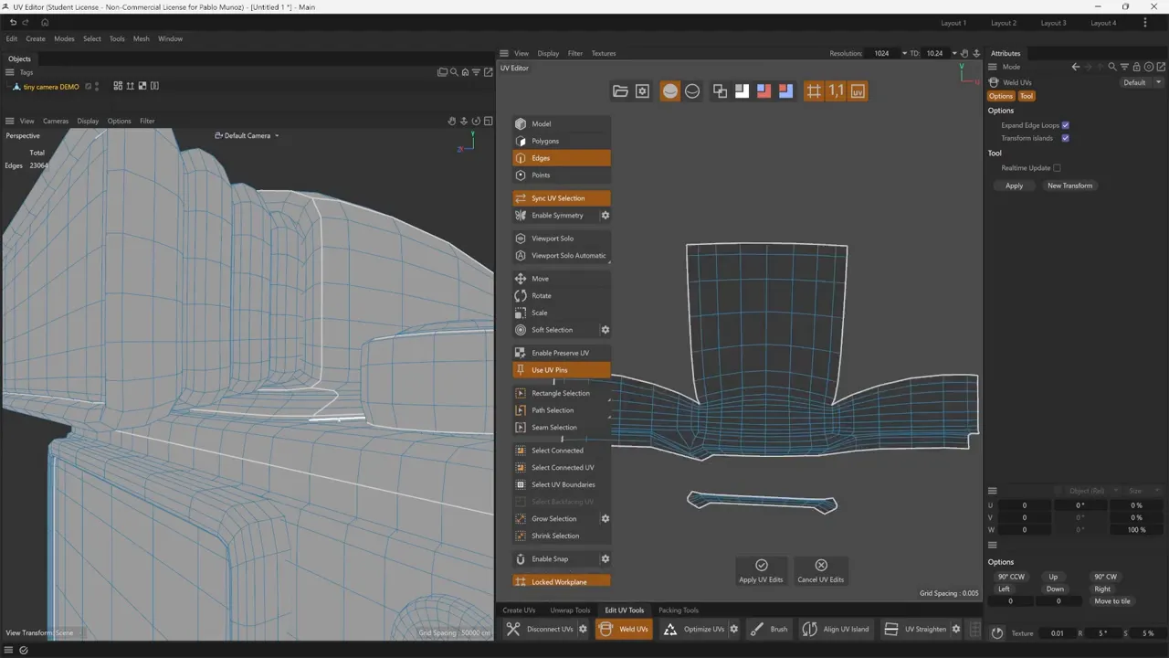
More continuity isn’t always better. A complicated shape may unwrap more cleanly as three simple islands than as one awkward piece. Use welding to improve the layout, not simply to reduce the island count.
Step 8: Load a checker and inspect distortion
A UV outline can look tidy while the texture still stretches. Open the 2D view’s gear menu, go to Textures, then choose Colour Grid or Checkerboard.
To use a custom checker, load it through the folder icon. Adjust its opacity if it competes with the wireframe, then enable the object’s texture tag to display it on the 3D model.
I like checker patterns with circles because deformation becomes easy to spot: circles turn into ovals, while evenly spaced cells reveal compression and stretching. The UV Checker Maker in the Pablander Academy tools can create custom patterns and export them as PNG.
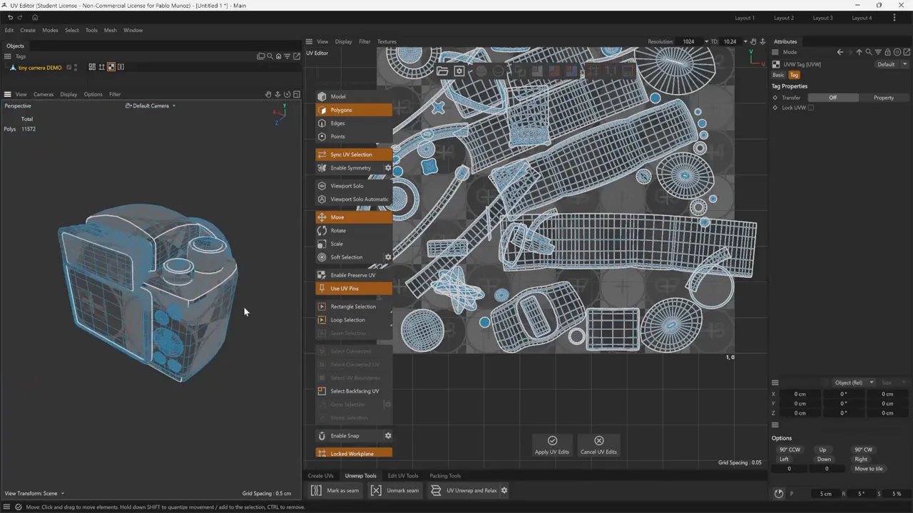
Use the checker alongside the editor’s diagnostics. Overlap, distortion and texel density are separate checks; red in an overlap display does not mean the same thing as red in the distortion display.
If a lens ring still resembles a distorted doughnut, inspect its side seam and unwrap it again. Fix the cut before trying to compensate by moving UV points.
Step 9: Align and rectangularize suitable strips
Once the islands flatten properly, open the editing tools. Align UV Island lets you click an edge to orient the island horizontally or vertically. It is much quicker than rotating every strip by eye.
UV Straighten straightens selected edges, but working through an entire strip edge by edge is quite manual. For suitable islands, select the whole region and use UV Rectangularize instead.
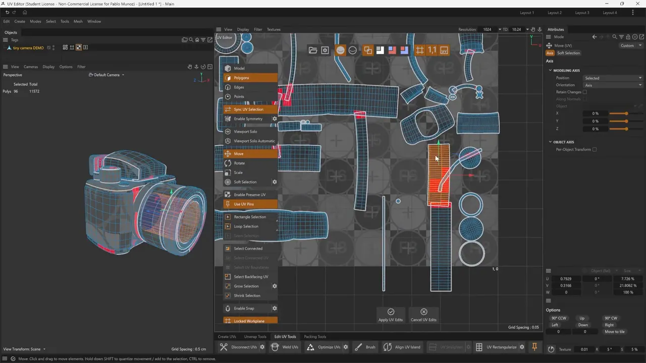
This works well on regions prepared to open into regular strips. It won’t work on every shape. A corner or incompatible cut can produce an error, and forcing a rectangle can introduce distortion.
If the result stretches too much, inspect the tool’s settings. In the camera example, disabling Auto Align and enabling Equidistant Distribution improves one difficult strip. Keep checking the texture… a curved island with less distortion can be better than a perfectly straight one.
Step 10: Pack the layout and set orientation constraints
Open Packing Tools and run UV Packing. Until this point, islands may overlap simply because you have been unwrapping and editing them without arranging the layout.
The Unwrap and Relax settings also include Pack Islands, but that provides a basic arrangement to avoid overlaps. Use the dedicated packing tools for the final layout.
Open the packing gear menu and review:
- Starting tile U and V: use 0, 0 for the starting tile. Change these coordinates to pack selected pieces into other UDIM tiles.
- Orientation: Free allows the packer to choose island rotations. Choose 90-degree rotation increments to preserve horizontal and vertical alignment.
- Scaling: Auto Fit fits the layout into the available space. Texel Density or Preserve Scale are relevant when maintaining density or an established scale across tiles.
For this camera, keep everything in one tile, use Auto Fit and restrict rotation to 90-degree increments after aligning the strips. Apply the packing, then inspect the model again.
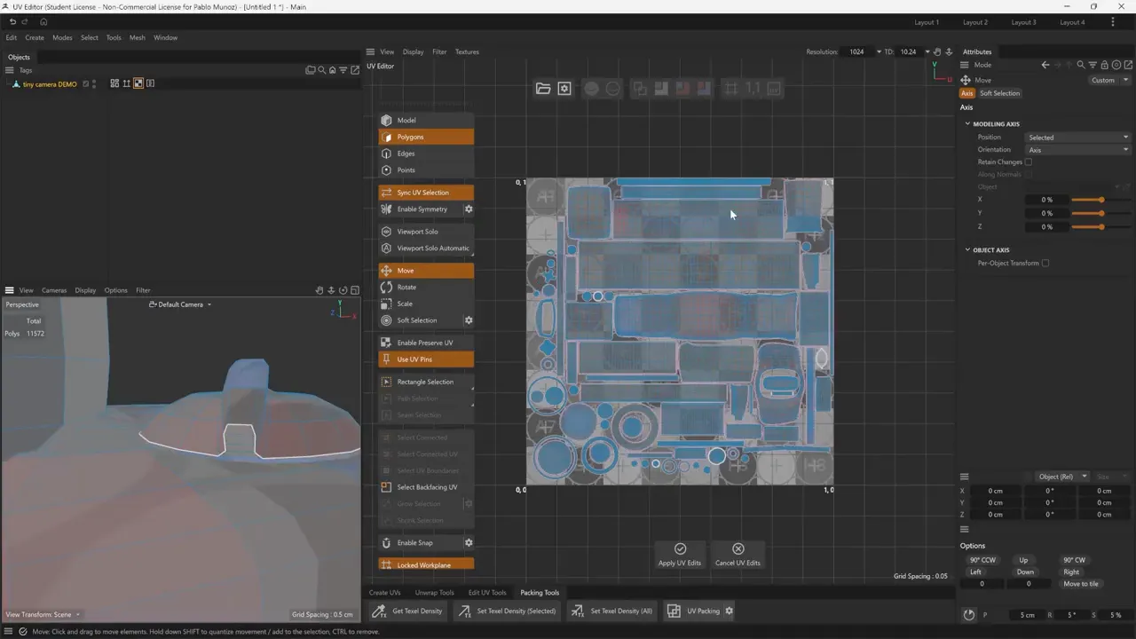
This works well on regions prepared to open into regular strips. It won’t work on every shape. A corner or incompatible cut can produce an error, and forcing a rectangle can introduce distortion.
If the result stretches too much, inspect the tool’s settings. In the camera example, disabling Auto Align and enabling Equidistant Distribution improves one difficult strip. Keep checking the texture… a curved island with less distortion can be better than a perfectly straight one.
Step 10: Pack the layout and set orientation constraints
Open Packing Tools and run UV Packing. Until this point, islands may overlap simply because you have been unwrapping and editing them without arranging the layout.
The Unwrap and Relax settings also include Pack Islands, but that provides a basic arrangement to avoid overlaps. Use the dedicated packing tools for the final layout.
Open the packing gear menu and review:
- Starting tile U and V: use 0, 0 for the starting tile. Change these coordinates to pack selected pieces into other UDIM tiles.
- Orientation: Free allows the packer to choose island rotations. Choose 90-degree rotation increments to preserve horizontal and vertical alignment.
- Scaling: Auto Fit fits the layout into the available space. Texel Density or Preserve Scale are relevant when maintaining density or an established scale across tiles.
For this camera, keep everything in one tile, use Auto Fit and restrict rotation to 90-degree increments after aligning the strips. Apply the packing, then inspect the model again.
RadialZ - Radial Menus for ZBrush
RadialZ puts your whole ZBrush library one gesture away. Press a hotkey and your brushes, alphas, textures and materials appear at your cursor. Click, hover or flick to pick, and stay in the flow.
Get resource
ZBrush 2027 Selection Sets
Selection Sets in ZBrush 2027 let you keep different versions of your polygroups, masks, PolyPaint, UVs and morph targets… all on a per-subtool basis. No need to rebuild a useful mask or sacrifice one polygroup layout just to try another.
Check it out